CAD/CAM Robotic Dental Crowning & Dynamic Registration Workflow
Autonomous Surgical Robotics at Bionics Lab UCSC
The CAD/CAM Dental Robotics project at the Bionics Lab, University of California, Santa Cruz (UCSC) focused on the development of an autonomous robotic system for semi-autonomous dental restoration. My research encompassed two primary areas:
- Dental Crowning Preparation: I developed a workflow to generate milling trajectories from 3D-digitized tooth models, enabling the robotic arm to autonomously mill a boundary around the tooth.
- Dental Implant Preparation: I extended this work to execute implant placement procedures. To account for patient movement during the procedure, I designed and implemented dynamic registration. This involved using a passive robotic arm (Microscribe MX) as a real-time feedback mechanism to track the position of the jaw.
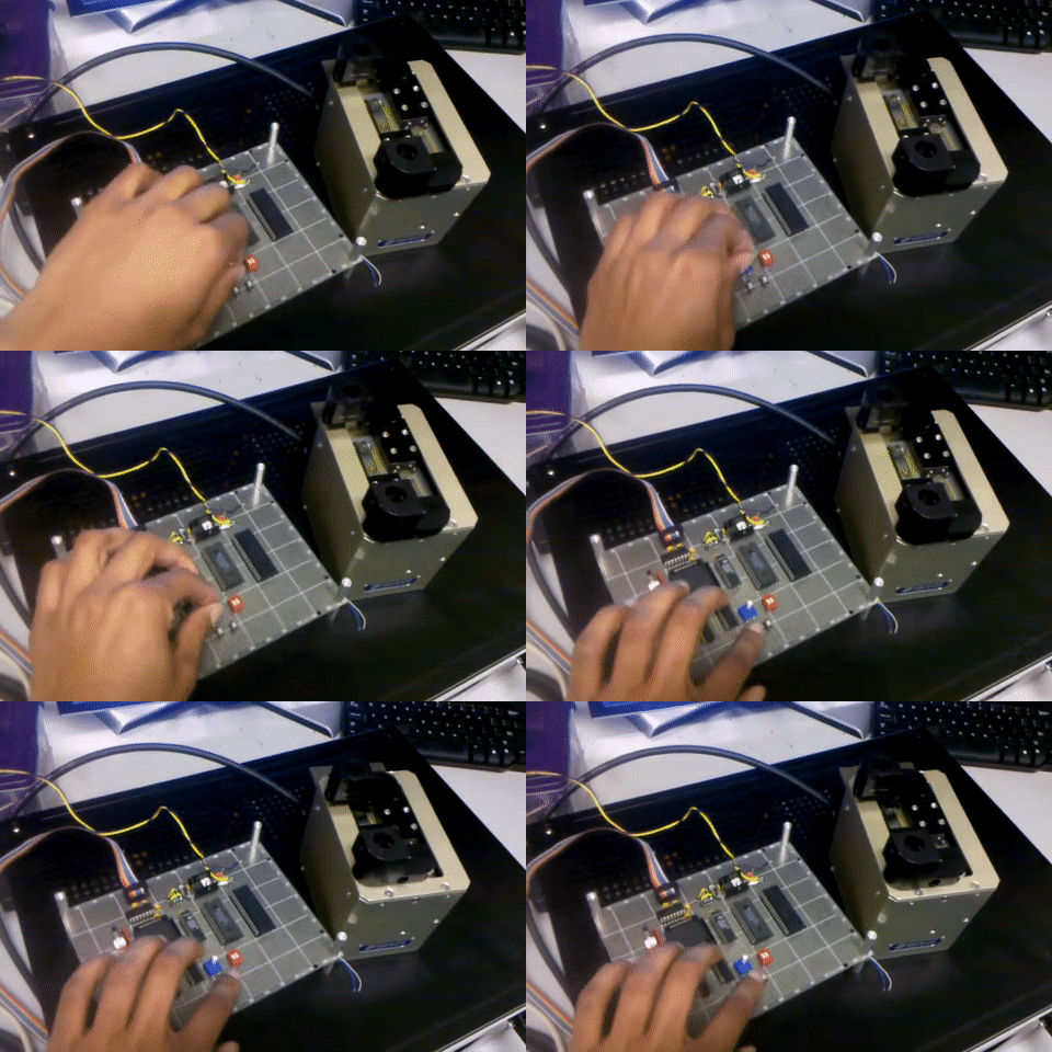
To facilitate this, I developed surgical control software—integrating Visual Studio, Matlab, and ORiN APIs—to synchronize the active robotic arm (Denso VM-B01G) with real-time positional data, allowing for high-precision milling and drilling aligned with patient-specific intraoral geometry.
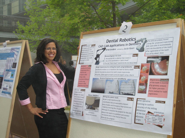
Figure 1: Robotic dental crowning experimental setup and software user interface at UCSC Bionics Lab.
Technical Context & Surgical Challenge
Traditional dental restoration and implant preparation rely on manual handpieces, impression molds, and mechanical jigs. Integrating industrial 6-DOF robotic arms (such as the Denso VM-B01G) with real-time tracking (via MicroScribe 3D digitization arms) enables sub-millimeter precision during enamel preparation and crown alignment.
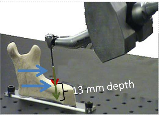
Figure 2: Architectural diagram of the dynamic registration dental robotics setup, featuring the Denso 6-DOF robot arm, MicroScribe tracking arm, and intraoral jaw model.
Key engineering challenges included:
- Dynamic Kinematic Registration: Continuously updating target coordinates as patient/jaw movement occurs during drilling.
- Homogeneous Transformation Chain: Computing frame transformations between the robot base, MicroScribe base, end-effector tool tip, and patient implant site.
- Safety-Critical Clinician UI: Providing real-time toolpath visual feedback, registration status monitoring, and emergency override controls.
Kinematic Formulation & Frame Calibration
To achieve precise alignment between the robotic tool tip and the target tooth site, I established coordinate frames across the arm and tracking sensor:
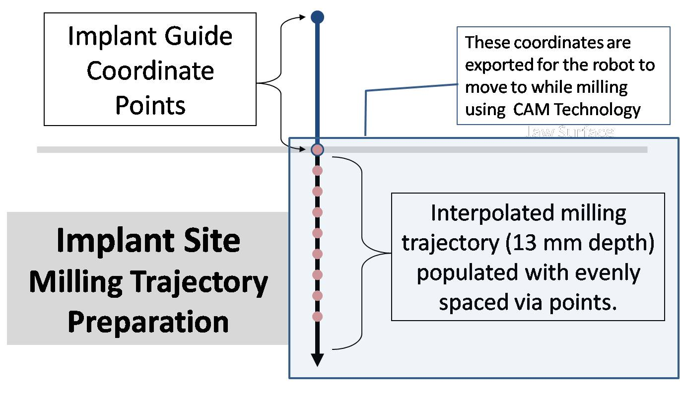
Figure 3: Kinematic coordinate frame mapping between robot base D{0}, end-effector D{6}, tracking base MX{0}, and tracking probe tip MX{6}.
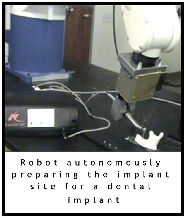
Figure 4: Kinematic transformation chain flow used to solve for relative tool-to-implant spatial transforms.
Homogeneous Transformation Math
I solved the spatial position of the target tooth implant site relative to the robot end-effector M6_P_ImplantLoc through the transformation chain:
T_Implant = T_D6_to_Base * T_Base_to_MXBase * T_MXBase_to_MX6 * P_TipWhere:
T_D6_to_Base: Forward kinematics matrix of the Denso 6-DOF arm.T_Base_to_MXBase: Static calibration transform between robot base frameD{0}and MicroScribe base frameMX{0}.T_MXBase_to_MX6: Joint position readout matrix from the MicroScribe tracking arm.P_Tip: Offset vector for the target point relative to the probe tip frameMX{6}.
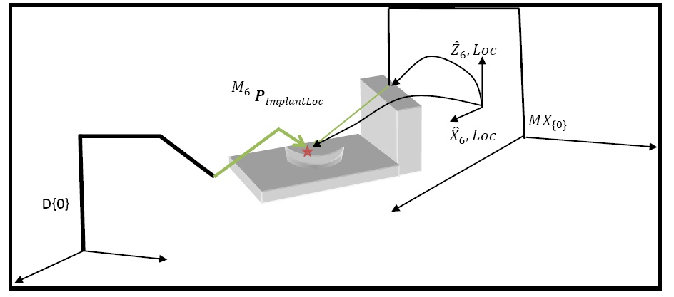
Figure 5: Vector transformation diagram mapping target implant location vector M6_P_ImplantLoc within the end-effector frame.
Closed-Loop Dynamic Tracking System
I implemented a closed-loop controller that continuously queries the tracking arm position and adjusts the Denso robot manipulator commands in real time.
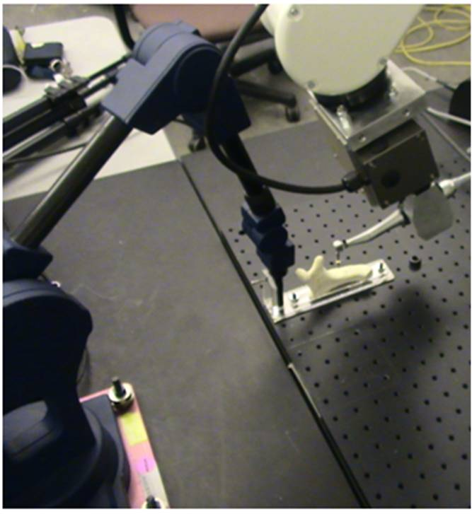
Figure 6: Closed-loop dynamic tracking control system diagram for real-time jaw motion compensation.
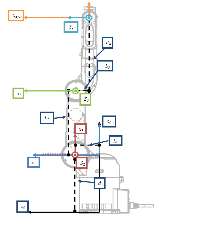
Figure 7: Real-time surgical monitoring software interface showing active frame tracking and toolpath progress.
Experimental Results & Tracking Accuracy
I benchmarked tracking accuracy across simulated patient motion profiles using anatomical dental phantom models.
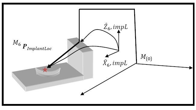
Figure 8: Measured 3D positional tracking error over time during dynamic compensation testing.
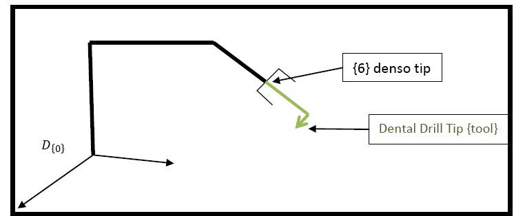
Figure 9: Alignment error distribution across experimental drilling trials, demonstrating sub-millimeter geometric accuracy.
Experimental results verified:
- Mean Spatial Tracking Accuracy: Sub-millimeter position accuracy (< 0.45 mm) across dynamic movement profiles.
- Control Loop Rate: Real-time compensation loop running at 100 Hz update frequency.
Video Demonstrations & Media
Downloadable Technical Report
Research Significance
- Demonstrated real-time dynamic registration for dental implant preparation and crowning.
- Verified sub-millimeter trajectory execution under clinician-in-the-loop oversight.